
Case Study
High Speed Compressor

The hydrocarbon compressor of the plant was driven by two power sources on a common shaft. One power source is a 20MW gas turbine and the other is the electric motor drive system. The original intention of adding an electric motor to the LNG train was to compensate for the reduced power output of the turbine due to the high ambient temperature during summer. This motor and drive system is referred to as the “Helper Motor Drive System” due to its original intended purpose. However, at present, the helper motor is utilized in all seasons to increase gas production. The original helper motor drive system was of Load Commutated Inverter (LCI) topology and they were manufactured by Toshiba over 25 years ago and had been in reliable service since the installation. Unlike most motor drives, the helper motor drive does not control the speed of the compressor train’s common shaft. The speed of the train is set/adjusted by the gas turbine. The speed range of the train is between 3250rev/min to 4905rev/min. The inverter synchronises with (i.e. captures) the spinning helper motor and controls the motor's mechanical power contribution to the train’s common shaft. The power reference to the helper motor drive is adjusted by the high-level process control system based on the production requirements.

Simplified Outline of Hydrocarbon Compressor Train
The main aims of replacement were to:
Extend the plant life by adopting modern inverter technology
Increase the production by increasing the capacity of helper motor from 4.2MW to 4.9MW
Reduced risk of process interruptions caused by unplanned outages due to ageing equipment and unavailability of parts
The replacement helper motor was a squirrel cage induction motor which is driven by a Voltage Source Inverter (VSI) topology drive system. Some challenges regarding this project were:
Replacement needed to be carried out in a short shutdown period. The new motor was designed to match the existing mounting with help of an adapter plate. The adapter plate eliminates the requirement for major welding or structural modification to the compressor base plate. The bearing lubrication oil pipe interfaces were designed to match with existing pipe installation on site.
The motor is located approximately 300 meters from the substation where the inverter is installed. The motor power and instrument cables are buried and laid in a congested path in the gas plant. The addition of new cables or modification to the existing buried cables would interfere with the operation of the rest of the plant and would attract very high installation costs. As a result, a requirement was formulated to reuse the existing power and instrument cables between the motor and inverter. The motor terminal boxes were carefully designed and located to eliminate the requirement for cable joints. Power cable entry locations and terminal heights of new inverter panels were matched to the original terminals. A marshalling panel was designed to enable easy termination of the existing instruments and LV power cables.
The original LCI was a 12-pulse output configuration with 2 x 3.3kV outputs. These two outputs were connected to the motor by two groups of cables; each group consisted of 4 x 3 core cables in parallel; total of 8 x 3 core cables per motor. The LCI controls the current of each output independently. This results in a near-equal magnitude of current in each output cable group.
Current sharing by each cable group was a great concern during the selection process of the new drive system due to the age of the buried cables. The new VSI output is of PWM waveforms which produce low torque ripples, and would not require phase-shifted motor windings. However, using 8 x 3 core cables in parallel presents a risk of potentially unbalanced current sharing and may cause overheating of cables. The new VSI was designed with two off 3000kVA drives feeding the motor through an output balancing reactor to achieve the current balance between each group of cables.
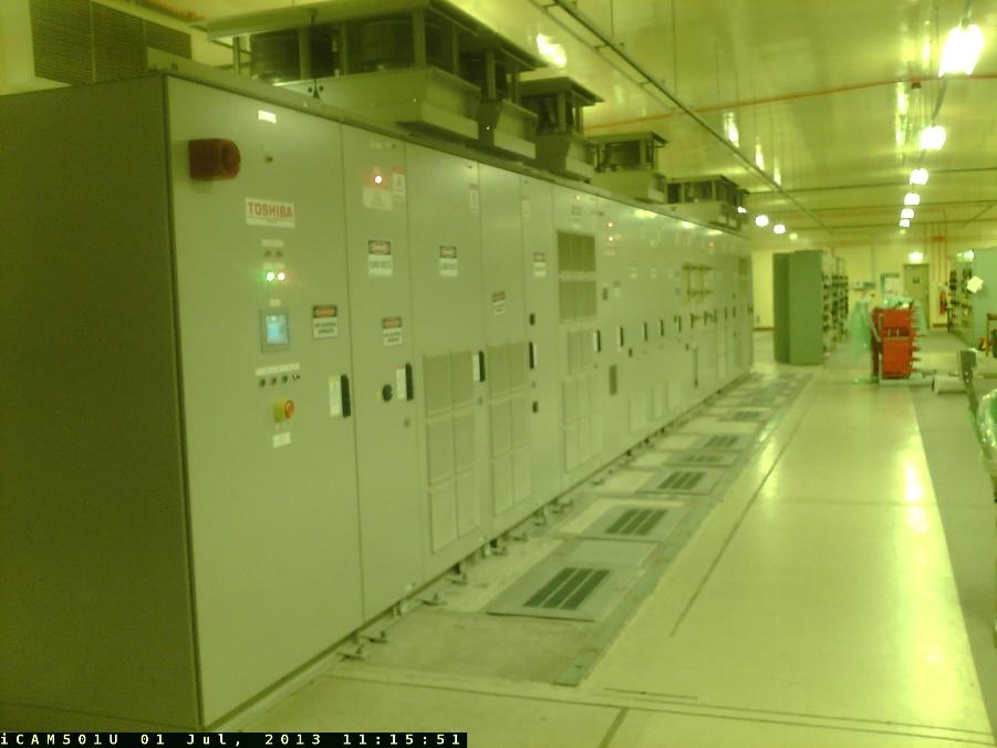
A customised version of Toshiba TMdrive-MVG inverter and a hazardous area-rated helper motor was selected to meet the customer’s specifications.
TMdrive-MVG drive installed in switchroom.
Safety was paramount to the design of the MVG2 inverter which included isolator and earth switches fitted to the output panel complete with a viewing window. The fortress locking system was incorporated and integrated with a site safety system
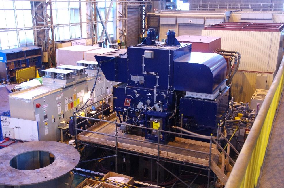
Full load string testing of the drive system was conducted at Toshiba Keihin works. The performance of the drive system exceeded the customer's expectations.
New helper motor drive system during string test.
Toshiba also provided site supervision and commissioning services for the motor/drive system during various aspects of the project including measuring the existing motors and drives.